


Four pages of this series have leaned on one promise: the mathematics has its own page. The bird eye view is built from a short chain of geometric facts, each simple on its own: light travels in straight lines, a lens bends by a measurable rule, a camera’s place on the body is six numbers, a flat floor lets every pixel be traced to one ground point. The chain explains what the screen shows, what it distorts and why the errors point the way they do.
No equations appear below. The working mathematics of a surround view lives in matrices and calibration files. A buyer never touches either. What a buyer reads on the screen are the consequences: straight kerbs rendered straight, distance bands that hold their width, a pole smeared into a wedge at a corner. Each consequence traces to one link in the chain, in words a workshop can use on a Tuesday morning with a complaint ticket in hand.
The debts come due here. The overview walked the pipeline and promised the projection its own page. The calibration page measured a lens profile to fractions of a degree without saying what the measured numbers describe. The seam page blamed geometric residuals for stepped lines without defining a residual. The regimes page weighed self-correction errors of a few degrees without showing what one degree does to a screen. Each debt gets its answer in its own section, against the same vocabulary those pages already use.
The whole screen is one sum: a bend, a stance, a flat floor.
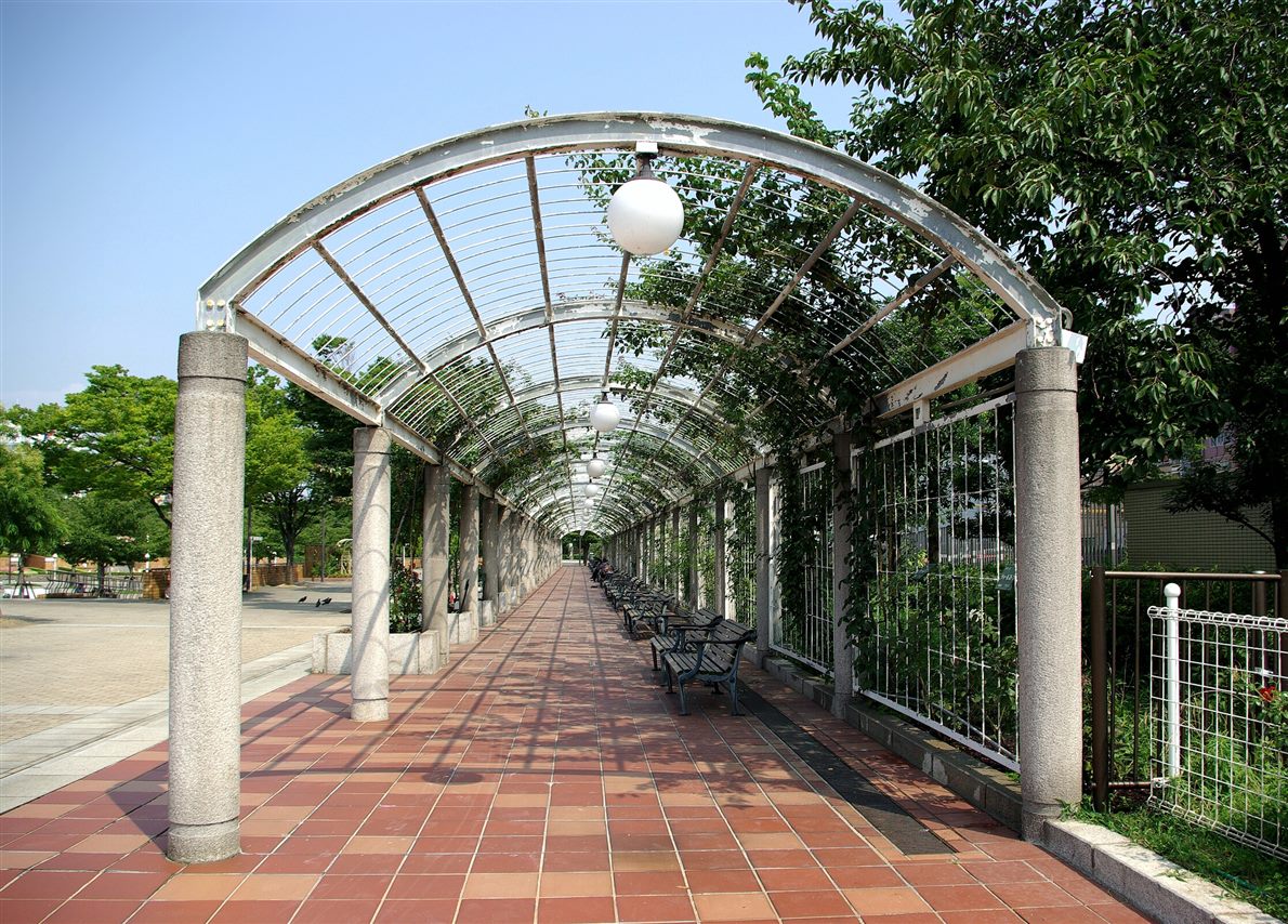
Every link in the chain rests on one physical fact: light travels in straight lines. A camera gathers the lines that pass through one point, the optical center. It records where each line lands on a flat sensor behind that point. That single sentence is the pinhole model, the oldest tool in the box. It already explains the photograph beside this paragraph, with no further machinery.
The explanation is a division. An object twice as far away subtends half the angle, its bundle of light lines arrives twice as steep, its image lands half as tall on the sensor. Image size equals true size divided by distance, scaled by one camera constant. The paving squares in the photograph are all the same size on the ground. The camera divides each by its distance, the near ones gently, the far ones hard, until the grid crushes into the vanishing point. Perspective is not a style. It is what division looks like.
Two of the calibration page’s measured numbers live in this model. The camera constant is the focal length, expressed in pixels: how many pixels of image height one unit of angle buys. The optical center is the point where the lens axis meets the sensor, the zero from which every image position is counted, off the geometric middle by manufacturing reality. With those two numbers, the pinhole model runs both ways: from a world point to its pixel, from a pixel back along its light line into the world. The backward direction is the one the rest of this chain spends. Every stage below starts from a pixel and asks where its light line came from.
The pinhole rule has a working limit. As a light line approaches ninety degrees off the axis, its image position runs toward the edge of an infinite sensor: the division stretches without bound. A lens that must see a full half-sphere, the requirement the overview set for four-camera coverage, cannot deliver its world onto a flat sensor by plain division. It needs a different rule for the bend, the rule the next section states.
The fisheye lens replaces division with a gentler bookkeeping. Where the pinhole model maps the tangent of the incoming angle, a mapping that explodes at ninety degrees, the fisheye maps the angle itself. The common design rule is plain to state in words: the distance from the image center to a point’s image grows in direct proportion to the point’s angle off the lens axis, with the focal length as the constant of proportion. Twice the angle, twice the radius. The published name is the equidistant projection.
The proportionality is what fits a half-sphere onto a chip. A point ninety degrees off axis, level with the lens, lands at a finite radius: ninety degrees multiplied by the focal constant. Some designs push past it. The bookkeeping holds out to the limits the overview quoted for surround lenses, the reason a single camera can watch a whole flank of a truck from one mirror arm.
The equidistant rule has published siblings, each trading the rim differently: one preserves area, one preserves shapes near the edge, one compresses the rim harder. Manufacturers pick a design curve from this family. Manufacturing then moves every individual lens a little off its design, the tolerance the calibration page measured per unit. The lens profile that page wrote, an optical center plus a handful of bend coefficients, is this section’s curve made concrete: the measured angle-to-radius rule of one physical lens, with its deviations from the catalog ideal recorded as corrections.
Distortion correction is the rule run backward. Take a pixel, measure its radius from the optical center, invert the measured curve to recover the incoming angle, restate that angle as a straight-line direction, place the result where a pinhole camera would have put it. Do the inversion once per output pixel and store the answers: that table is the remapping the calibration page’s runtime section described, its mathematics now visible. Nothing in the inversion depends on the scene. The table survives unchanged from frame to frame for that reason.
The rim cost the overview admitted falls out of the same rule. Equal angles get equal image radius. Equal angles near the horizon cover far more ground than equal angles near straight down. A pixel at the rim answers for more meters of world than a pixel at the center. Correction can restate positions exactly. It cannot mint detail the rim pixel never recorded, the arithmetic behind the composite’s softer outer ring.
The regimes page weighed errors in camera pose without defining one. The definition is short. A pose is six numbers: three say where the camera sits in the vehicle’s own coordinate frame, measured from a fixed body reference, three say which way it points, a rotation about each axis. Position and orientation, nothing else. Every claim that page made about frozen parameters and drifted brackets is a claim about these six numbers per camera.
The six numbers split cleanly from the lens profile of the previous section. The split carries the maintenance logic of the whole series. The profile, optical center plus bend coefficients, belongs to the lens as a part: it changes when glass changes. The pose belongs to the installation: it changes when metal moves, a nudged bracket, a body repair, a remount. The calibration page measures both families in one session. The trigger list treats them differently because physics does: knocks move poses far more often than they reshape glass.
The cloth session solves the six numbers from their signatures in the image. A camera mounted higher sees the laid pattern smaller. One angled down sees it foreshortened. One rotated sees it turned. Each effect is the pure trace of one pose component. The solver adjusts its six candidate numbers until the predicted pattern matches the photographed one. The reprojection residual that page reported is the leftover mismatch after the best fit, measured in pixels: the definition the seam page borrowed and this sentence now supplies.
Four cameras mean four poses, all expressed in the same body frame, written in millimeters and degrees in the configuration record. The shared frame is the quiet foundation under the seams. Two neighboring cameras can argue about one ground point only because both report positions in the same coordinates, anchored to the same body reference. A pose written in the wrong frame, or a body reference moved by repair, breaks the comparison before any lens mathematics gets a vote. The seam page’s geometric residual now has its mathematical name: the gap between where two poses, each correct to within its own measurement error, place the same ground point on the shared grid.
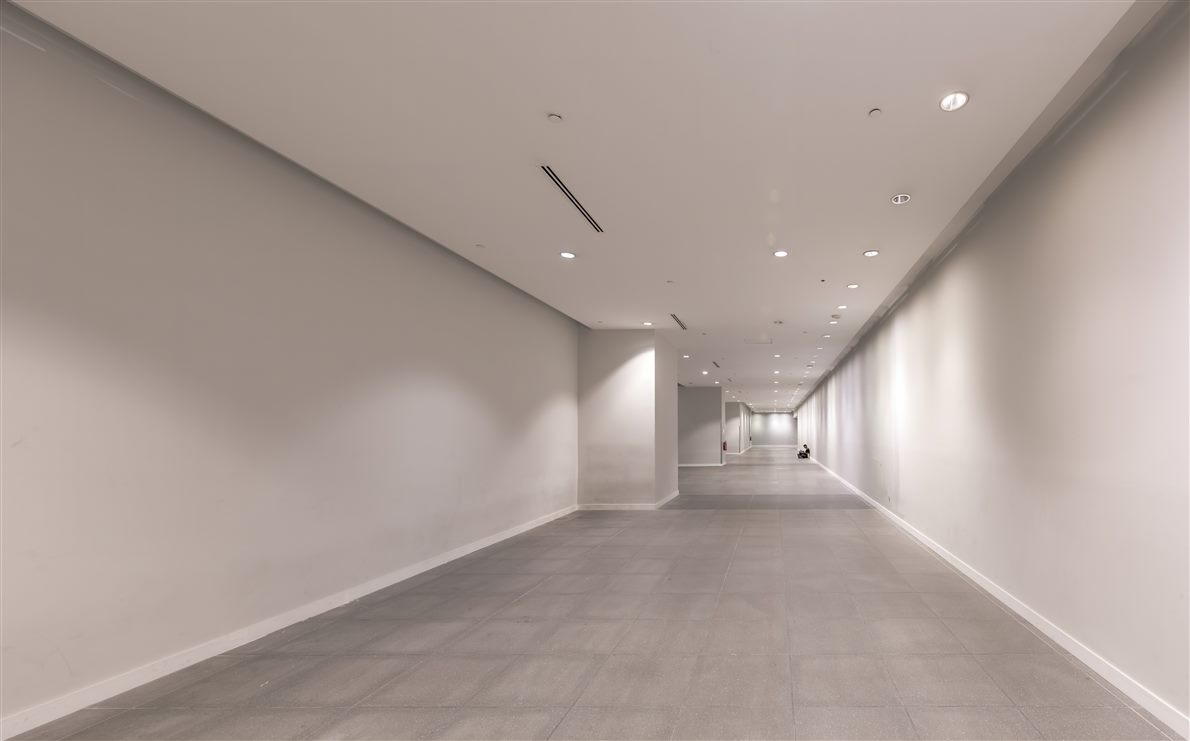
The chain now assembles. The assembly is the paragraph the overview promised: the mathematics that turns a corrected camera picture into a patch of bird eye view. Start with one pixel of one camera. The lens profile turns its image position back into an incoming angle, the previous sections’ rules run in reverse. The result is a direction: a straight light line entering the camera from somewhere in the world. On its own the line is not a place. Every point along it, half a meter away or fifty, would have lit the same pixel, the depth ambiguity every single camera carries. The system breaks the ambiguity with an assumption it states once and spends everywhere: the mapped world is the ground, the ground is flat, the camera heights above it are known, all of it carried by the six pose numbers of the section above. Under that assumption the light line can be followed out of the camera, expressed in the vehicle’s body frame and extended until it meets the ground plane. A line and a plane meet at exactly one point, an intersection a stretched string could demonstrate on the floor. That point’s body-frame coordinates are the pixel’s ground address: so many meters ahead of the reference, so many to the side. The bird eye view is then a bookkeeping exercise: a regular grid laid over the ground around the vehicle, one output pixel per grid cell, each cell recording which camera pixel’s ground address lands there. The corridor photograph shows what the exercise undoes. Each floor tile images at its true size divided by its distance, near tiles large, far tiles vanishing, the plain perspective of the first section. Tracing every pixel’s ray back to the floor multiplies each tile by its own distance again: in the output grid every tile renders at one size, the way a true overhead photograph would show it. The literature calls the whole operation inverse perspective mapping, IPM, the name read literally: perspective divided, the mapping multiplies back. The same literature treats it as a coordinate change between the image plane and the bird eye plane, the bridge the next section crosses. The cost of the trick is the assumption itself. The intersection is only as true as the flatness and the heights that produced it, the single fact from which the loading errors of the regimes page, the slope errors of the calibration page and the height smearing of the section below all descend.
The ray-tracing story of the last section is the truth. Implementations compress it. For points on one plane seen by one camera, the whole chain from image position to ground position collapses into a single fixed recipe, a three-by-three grid of numbers the literature calls a homography: the standard name for a projective mapping from one plane to another. Feed it an image position, get back a ground position, one small matrix multiplication per pixel. The recipe exists only because the ground is a plane. Planarity is the precondition.
A homography carries eight independent numbers. The grid holds nine, with one spent on overall scale, leaving eight that matter. Eight numbers need eight knowns. Each matched point pair, this image position equals that ground position, supplies two. Four point pairs, no three of them on one line, pin the mapping completely. Four is the floor, the minimum the arithmetic demands. The cloth session hands the solver hundreds of pairs from one laid pattern. The surplus averages out the pixel-level noise of any single detection and leaves a measurable leftover, the residual the calibration page reads as its quality number. A mapping pinned by four points is determined. A mapping fitted over hundreds is determined and graded.
Four corners deciding an entire plane is the working consequence the workshop already uses. Four ground points marked at taped distances, four noted image positions: the whole floor’s mapping follows, every tile, every bay line, every point in between. The published toolchains state the same fact in reverse: with the lens profile known, a solved homography can be unpacked back into the camera’s pose, the six numbers of the earlier section recovered from one matched plane.
The seam page’s open question closes here. Two neighboring cameras each carry their own homography to the same ground plane, built from their own poses. Apply both: the same painted line arrives on the shared bird eye grid twice, from two directions. With healthy parameters the two arrivals agree to within the measured residuals. The overlap comparison that the whole seam and color machinery feeds on is two homographies pointed at one floor.
The ray tracing of the mega section assumed every pixel saw the ground. The pixels that saw something raised get processed by the same arithmetic. The arithmetic answers wrong by rule. Take the top of a bollard a meter tall. Its light line enters the camera from above the ground. Extended to the ground plane, the line lands beyond the bollard’s true position, on the far side from the camera. The projection prints the bollard’s top meters past its base.
Because the base sits on the ground, the base projects true. Every point up the bollard projects progressively farther out, along the line running from the camera’s foot through the bollard’s base. The render is a smear: a vertical object laid flat on the grid, pointing away from its camera, longer than the object is tall. Four cameras smear in four directions, the radial splay every composite shows around its edges. The bird eye view spends height as length, the rate set by the camera’s own height and the object’s distance.
The seam page’s doubling is the same theorem run twice. A raised object in an overlap is smeared by each camera along each camera’s own direction. The two smears start from the same true base, head different ways, land in different cells. Two soft copies on the screen are two ground-plane intersections of light lines that never came from the ground.
None of it is a defect to repair, the point the overview made as driver training and this page makes as geometry: a single ground-plane projection has no slot for height, by construction. The honest reads follow from the construction too. Bases are true where the object touches the floor. Smears point away from their camera. Doubling happens only in overlaps. A trained eye uses all three rules the way the workshop uses the fault families, as a sorting key handed out by the mathematics itself.
The regimes page traded in degrees of pose error without stating what one degree does. The conversion tool is a lever. The lever is built into the ray tracing. A camera looks down at nearby ground steeply. It looks at distant ground at a grazing angle, the light line almost parallel to the floor. Tilt that grazing line by a small angle and its intersection point slides a long way along the ground before the line meets the floor again. The shallower the angle, the longer the slide. Distance multiplies tilt.
The numbers are workshop arithmetic, stated here for a camera mounted at two meters. For ground five meters out, a tenth of a degree of pitch error moves the projected point by roughly three centimeters. One full degree moves it by about a quarter of a meter. Three degrees, the working tolerance the regimes page quoted for texture-based correction, moves it close to a meter. At ten meters out, the same single degree costs roughly a full meter. The lever lengthens with range, the reason every page in this series checks accuracy at the far tape marks and expects the outer ring to fail first.
Height error moves the screen differently. The difference is a diagnostic. A camera that believes itself at two meters when loading has pressed it to one point ninety five projects every ground point closer by the same fraction, two and a half percent everywhere: twelve centimeters at five meters, twenty five at ten. A pitch error grows with range. A height error scales with range. Bands that stretch by one ratio across the whole quadrant say stance and loading. Bands that drift worse the farther out you read say tilt. The screen tells the two apart for anyone who measures it twice.
The same lever sets the standard the calibration page’s residuals answer to. A solved pose good to a tenth of a degree holds the five-meter band to centimeters, the accuracy class the acceptance tape checks can confirm. A pose off by the degrees a knocked bracket produces fails the same checks by margins a tape measure reads without effort. The mathematics is what makes the cheap test conclusive.
Every link above is fixed once the parameters are written: the bend rule per lens, the six numbers per camera, the plane, the output grid. A chain of fixed steps composes into one fixed answer per output pixel. Implementations compute the whole chain once at configuration time and store the result: for each cell of the bird eye grid, the source camera and the exact source position within its frame. Four cameras fill four quadrants of one shared table, with the overlap cells carrying two sources and the blend weight the seam page described, stored in the same pass. The lookup tables of the calibration and seam pages are this page’s mathematics, frozen.
The stored position lands between source pixels. Production tables carry it at sub-pixel precision, with the renderer blending the neighboring pixels it points into, the standard interpolation that keeps painted lines smooth on the grid. Table density matches the output: one entry per output pixel, at whatever grid resolution the product draws, each cell a few centimeters of ground on typical commercial layouts. A full-screen view of around a million output pixels carries a table of the same length, a few bytes per entry, a memory line item the imaging hardware reads in strict order every frame.
The freeze is the bridge to the regimes page. A table rebuilds only when a parameter changes, a re-measured pose or a swapped lens profile. No rebuild happens in traffic. Each rebuild lands in the configuration record as a dated version, the audit trail that page demanded. The mathematics runs once, at calibration time. Runtime replays the stored answers.
Three questions take the mathematics into a purchase document, each answerable in one line. Which projection family do the lenses follow, with the per-unit profile measured and stored, the equidistant rule or a stated sibling. What residual did the calibration solve achieve, in pixels, the grade of the whole geometric chain. What does one output pixel cover on the ground, in centimeters, with the far-band accuracy stated at a named distance, the lever’s working figure. A supplier fluent in those three answers has the mathematics of this page under control.
The chain stays short. A bend measured per lens, a stance of six numbers per camera, a floor assumed flat: everything the screen shows is those three facts multiplied through one another, frame after frame. Every sibling page hangs off one link: the calibration page measures the first two facts, the seam page spends them, the regimes page guards them, every page after this one lives with the third. The mathematics is not the product’s mystery. It is the product’s skeleton.
It answers one question per pixel: which point on the ground sent this light. The lens profile converts the pixel’s position back into an incoming angle. The camera’s measured pose converts that angle into a straight line in the vehicle’s coordinate frame. Extending the line to the ground plane gives one intersection point, the pixel’s ground address. The bird eye view assembles those addresses onto a regular overhead grid, one cell per output pixel. Equal floor tiles that imaged at shrinking sizes render at one size again, the perspective division multiplied back out.
A single camera cannot tell how far along its light line a point sits. The flat-ground assumption breaks that ambiguity: with the floor a known plane and the camera’s height known, every light line meets it at exactly one point. The intersection is only as true as the assumption. A slope tilts the real floor away from the assumed plane and the computed addresses slide. A raised object puts its pixels on light lines that never came from the ground. The arithmetic prints them beyond their true position, the smearing every composite shows.
Intrinsic parameters describe the lens and sensor as a part: where the optical center sits on the chip, how strongly image radius grows with incoming angle, the bend coefficients of the measured curve. They change when glass changes. Extrinsic parameters describe the installation: six numbers per camera, three for position in the body frame, three for orientation. They change when metal moves, a knocked bracket or a body repair. The calibration session measures both families at once. The trigger list watches the extrinsic side because knocks outnumber lens damage.
The lever depends on range and mounting height. For a camera at two meters, one degree of pitch error moves the projected ground point by roughly a quarter of a meter at five meters out, close to a full meter at ten. A tenth of a degree, the residual class a healthy calibration reaches, holds the five-meter error to a few centimeters. The growth with range is the reason acceptance checks read the far tape marks first and the reason the composite’s outer ring degrades before its center under any drift.
The standard name for a fixed projective mapping between two planes, held as a three-by-three grid of numbers with eight that matter. Here it maps the corrected camera image of the ground plane onto the bird eye grid. Four matched point pairs, no three on one line, pin it completely. A calibration session over-determines it with hundreds of pattern points and reads the leftover misfit as its quality number. Two neighboring cameras carry two homographies to one floor, the comparison the seams and the color loop both feed on.
No. Every step is fixed once the parameters are written. Implementations pre-compute the whole chain into a lookup table at configuration time: source camera, source position and blend weight per output cell. At runtime the imaging hardware replays the table, frame after frame, with no estimation in the loop. The table rebuilds only when a parameter changes, a re-measured pose or a swapped lens. Each rebuild lands in the configuration record as a dated version. The lifecycle of those parameters is the regimes page’s whole subject.