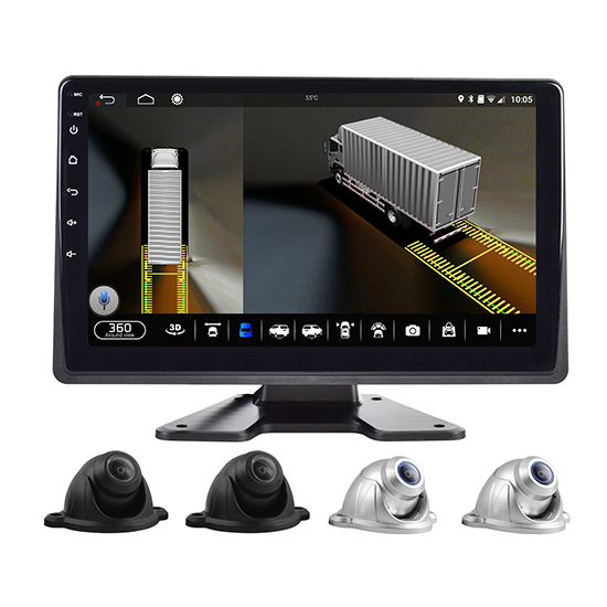
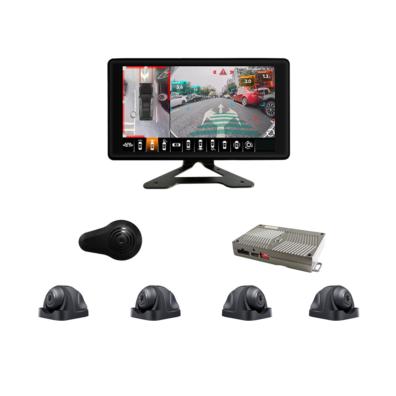
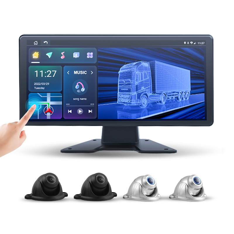
The screen shows the vehicle from above, in the middle of a continuous picture of its own surroundings, with no aircraft anywhere. Four wide-angle cameras on the body produce that picture, through a fixed sequence of geometric steps the system runs on every frame. The whole sequence matters, because every behaviour of the finished view, the clean ring of ground, the stretched shapes at the edges, the faint doubling at the corners, follows from one of its steps. The pipeline below runs once end to end. The sibling pages of this series then take each stage apart.
The around-view idea is older than its current ubiquity. The first production system shipped in 2007 on Nissan vehicles as the Around View Monitor, the name the abbreviation AVM still carries. The arrangement has not changed since: four cameras, one composite, a synthetic overhead viewpoint built for low-speed work. What changed is the spread, from luxury saloons at launch to delivery vans, buses, tractor units and the commercial fleet classes this series serves today.
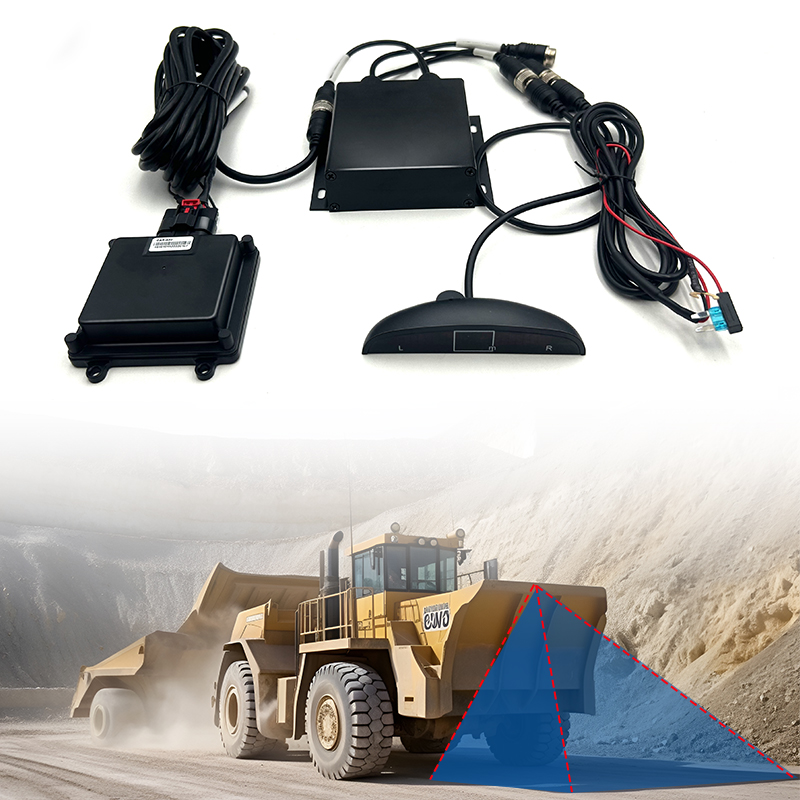
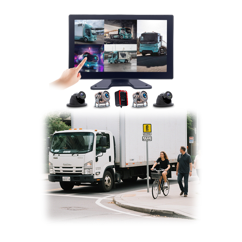
The duty is near-field and low-speed by design. The view covers the metres around the body, the zone mirrors and glass cannot fully show from the seat: the kerb against the wheels, the bollard behind the bumper, the child beside the front axle, the dock edge at the tail. Parking, tight-yard manoeuvring and pull-away checks around the wheels are the use cases the geometry was built for. Highway perception belongs to other sensors and other pages.
One honest sentence frames everything below. The bird eye view is a reconstruction, computed from four ground-level cameras under one strong assumption. It is accurate exactly where that assumption holds. Where the assumption breaks, the picture bends in predictable ways a trained driver reads through. The pipeline, the assumption and the bending are the three subjects below.
Four cameras look outward. One picture looks down.
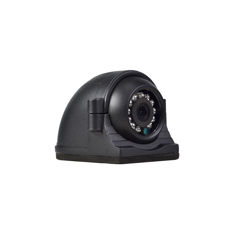
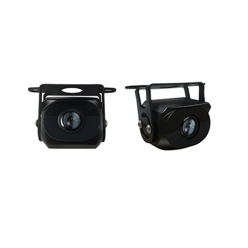
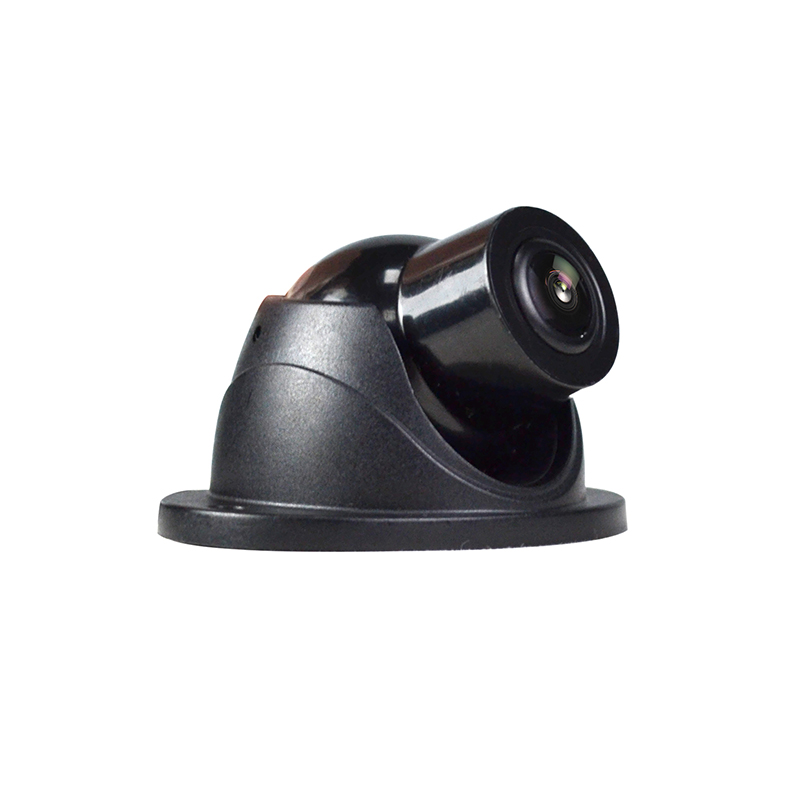
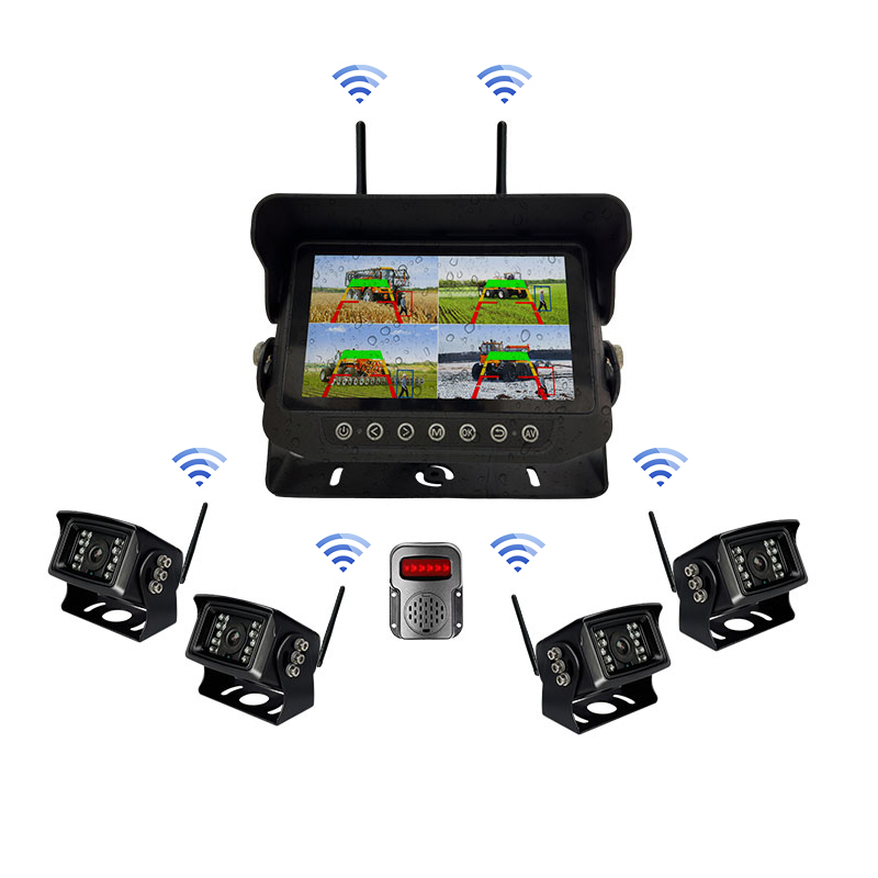
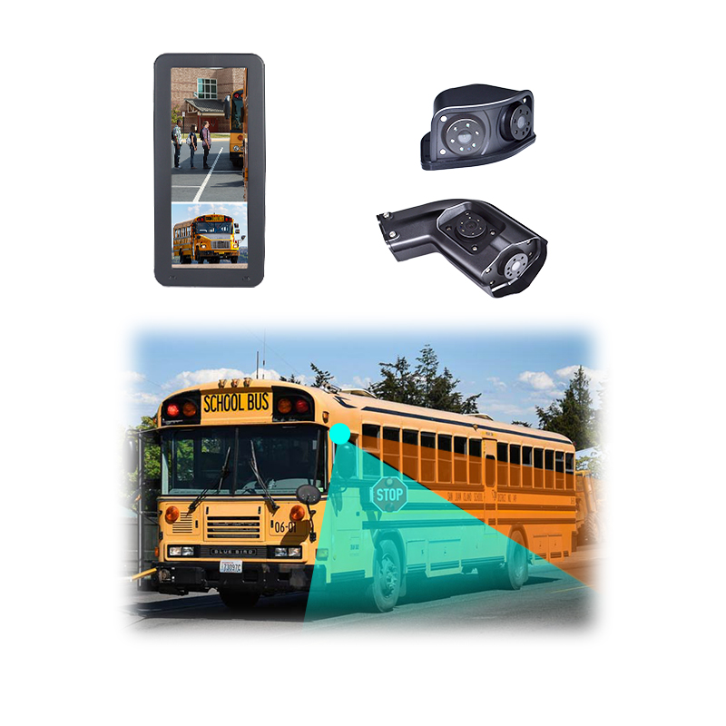
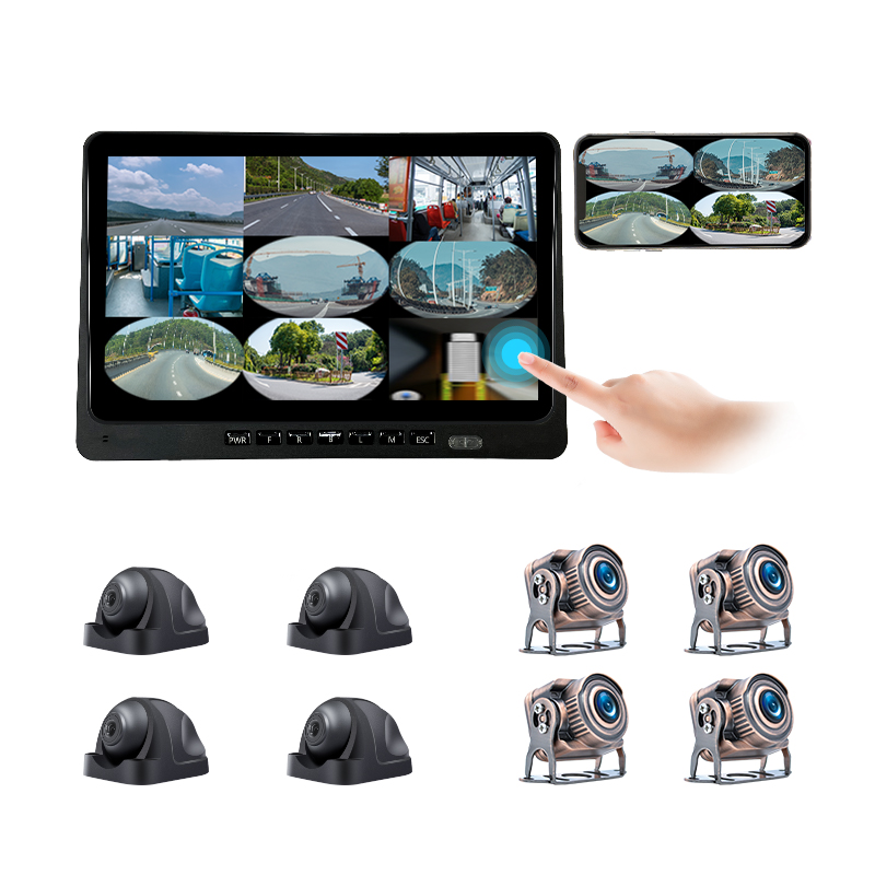
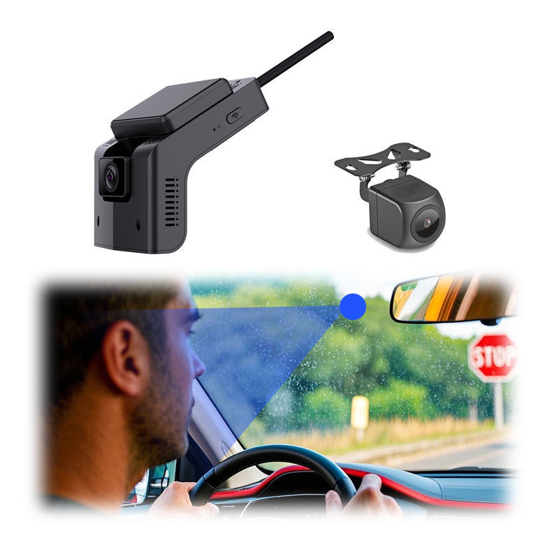
The four cameras sit at the body’s four faces. One looks forward from the grille or the cab front. One looks rearward from above the number plate or the door frame. Two look sideways and downward from the mirror arms or the body flanks. Each carries a fisheye lens with a field of view past one hundred and ninety degrees, the figure the surround-view literature settles on, wide enough that each camera sees past straight-out to slightly behind its own mounting plane.
The wide fields are what close the ring. Four cameras at ninety-degree spacing with ordinary lenses would leave four blind wedges at the corners. Four fisheyes at one hundred ninety degrees and more overlap generously at every corner instead: the front camera and the left camera both see the left-front quarter, the rear and the right both see the right-rear. Every point of ground around the body lands in at least one camera. The corner zones land in two.
The double-covered corners are a feature the pipeline spends deliberately. Overlap is where the composite must decide between two sources showing the same patch of ground, the seam question one sibling page owns in full. Overlap is also what makes alignment checkable: two cameras claiming the same kerb must place it in the same spot on the composite, the property calibration tunes and the acceptance walk below reads with a cone and a tape measure.
Mounting height shapes each camera’s share. The mirror-arm cameras sit high and see a wide band of ground beside the vehicle. The grille camera sits low and close to its ground, with the steepest stretching at distance. Commercial bodies move these positions around, high cabs, long rear overhangs, equipment in the way of the clean mounting spot, the packaging differences the heavy-vehicle sibling page treats as its whole subject in detail. The pipeline below stays the same wherever the cameras land.
Four is the working minimum, the reason it became the standard count. Three cameras leave a corner uncovered or stretch fields past usable distortion. Six or eight appear on long commercial bodies where one side camera cannot see the whole flank, the multi-camera extension the articulation and trailer sibling pages pick up. The arithmetic above, one camera per face with corner overlap, carries over to those counts unchanged.
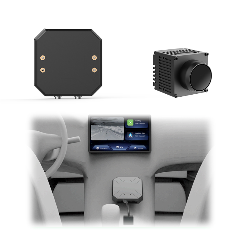
The pipeline runs six stages on every displayed frame. Each stage has one job. Stage one is synchronised capture. The four cameras expose at the same moment, within a tolerance the system enforces frame after frame, so the four images describe the same instant of a moving world around the body. Frames captured out of step would hand the later stages four slightly different worlds, a kerb in two positions, a pedestrian mid-stride twice over, errors no later mathematics can repair. Stage two is undistortion. Each fisheye frame arrives with the lens’s curvature baked in: straight kerbs bowed, poles leaning, the whole near world wrapped toward the frame’s edge. The undistortion stage applies the lens’s measured profile in reverse, straightening the bow into a frame an ordinary geometric step can use. The lens profile comes from measurement, the correction model and the calibration cloth that measures it being the second sibling page’s whole territory. Stage three is the ground-plane transform. The undistorted frame still shows the world from the camera’s own low mounting viewpoint on the body. The transform re-projects it onto a flat ground plane as seen from above, the step published methods call inverse perspective mapping: every pixel is cast down onto the spot of ground it would occupy if everything in the image lay flat on the surface of the road. The mathematics of that projection, homographies and the assumptions inside them, fills the fifth sibling page. Stage four is registration. Four transformed patches of ground now exist, one per camera, each one in its own local coordinates. Registration places them on one common ground grid so that the left camera’s kerb and the front camera’s kerb land on the same drawn line. The placement parameters come from calibration, the measured positions and mounting angles of each camera on the body, the regime question, calibrate once at fitting or refine continuously in service, that the fourth sibling page weighs in full. Stage five is seam handling. In the four corner overlaps two transformed patches claim the same stretch of ground. The system chooses a dividing line, blends across it, then matches brightness and colour between neighbouring cameras so the join reads as one continuous surface, the craft the third sibling page covers seam by seam. Stage six is composition. The four patches render into one canvas, the vehicle graphic drops onto the centre, guide lines and steering overlays draw on top where fitted, then the finished frame goes to the screen. The six stages then repeat for the next displayed frame, at the cadence and latency figures the seventh sibling page measures and prices.
The raw frame is a curved world. A fisheye lens trades straight lines for coverage: it accepts light from nearly a half-sphere and maps it onto a flat sensor. The only way that mapping fits is by bending. Lines through the centre stay straight. Everything else bows outward, harder toward the edge, until the world at the rim wraps almost sideways. The frame holds an enormous field, with the look of a reflection in a polished ball as its cost.
The bending is regular, which is what saves it. The lens bends light by a fixed profile, the same curve every frame, measurable to fractions of a pixel. Undistortion is the application of that measured profile backwards, computed once per lens at calibration and applied to every frame in real time after. What cannot be recovered is evenness: the fisheye spends its pixels densely at the centre and thinly at the rim, so the corrected frame is sharp near the camera’s axis and progressively softer toward its edges.
The fisheye wins the position despite the bending because the alternative costs more. Covering one face of a vehicle with conventional narrow lenses would take several cameras, several mounts, several cables and a stitching problem inside each face before the four-face stitch even starts. One fisheye per face buys the whole half-sphere in one part, with the bending handled once in software against a measured profile. The lens choice is the system’s first economy, the reason every production system since the first has made it.
The rim’s thinness sets a real limit the composite inherits. The ground far from each camera is drawn from the thin edge pixels of a stretched frame, which is why the bird eye view’s outer ring looks softer than the ground beside the body. The usable radius of the view is a lens-and-mounting fact, commonly a handful of metres of crisp ground shading into rough indication beyond, the near-field duty boundary restated in pixels on the screen.
The transform stage works under one assumption: everything in the frame lies flat on the road. For the road itself, the kerbs, the painted lines and the drain covers, the assumption holds exactly. Those features land on the composite in their correct positions at their correct sizes. The bird eye view is, for ground, an honest map. Steering against painted bays and kerb lines off the composite works because the geometry under them is exact.
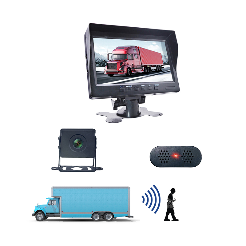
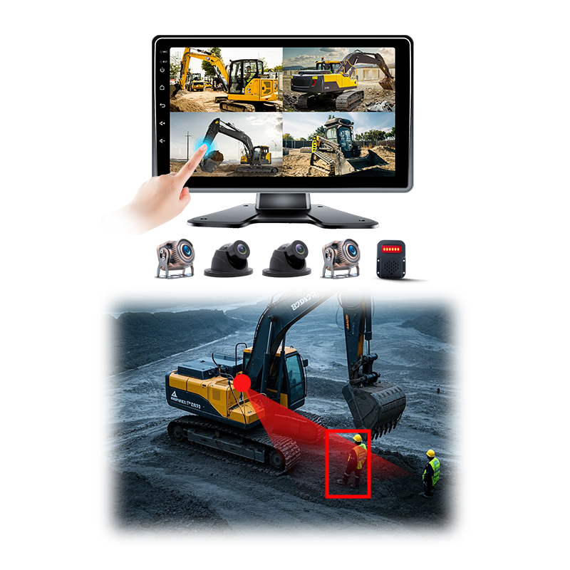
Anything above the ground breaks the assumption in proportion to its height. A standing person is mostly above the plane, so the projection smears the body outward along the line away from the camera: feet roughly correct, head flung metres further out. A bollard becomes a radial streak. A wall becomes a fan. The composite shows where tall things meet the ground correctly, with the thing itself drawn as a stretched shadow pointing away from whichever camera saw it.
Between flat and tall runs a gradient the eye learns quickly. A kerbstone a hand high distorts so little the view places it cleanly, the reason kerb work off the screen is reliable. A wheel stop reads true. A waist-high barrier begins to lean outward visibly while its base stays put. The trust gradient follows height above the road: centimetres are honest, knee height leans, head height smears. Drivers calibrate to it within a shift, with the training paragraph naming what they are seeing.
The corner overlaps add a second artifact to tall objects. A person standing in a corner zone is seen by two cameras from two angles, smeared along two different directions. The seam logic must pick or blend between them. The result reads as a doubled or split figure at the seam, present in every system to some degree, managed in the better ones, the behaviour the seam sibling page grades implementations by.
The honest reading is a training point, one paragraph in driver induction. The composite is exact for everything painted on or lying on the road, indicative for everything standing above it: stretched shapes mean tall objects, their root on the ground is where they touch it, their smear is geometry doing its work, with no malfunction in it. A driver who reads the view this way gets centimetre lane work and reliable obstacle awareness from the same screen. One who expects photographs from above reports ghosts.
No camera sees the vehicle’s own roof, so the vehicle in the centre of the view is a stored graphic. The system draws the composite ground ring first, then places a scaled top-view image of the vehicle over the hole in the middle where no camera coverage exists. The graphic is selected and scaled at commissioning to match the body’s real footprint, the dimensions the calibration records carry beside the camera positions.
The sprite’s accuracy is a real specification item, because the driver steers the real edges by the drawn ones. A graphic narrower than the real body invites kerb strikes the screen said were clear. A generic car shape under a box-bodied truck misleads at every corner of every manoeuvre. Commercial fittings use body-matched outlines, with the footprint dimensions checked against the real vehicle at acceptance, the tape-measure line in the walk below this section.
The sprite also defines what the view cannot show. Loads that overhang the body, an open tail lift, a swung door, exist outside the stored outline and inside the camera blind hole, so the composite neither draws nor warns about them. Bodies that change shape in service, tippers, cranes, articulated combinations, push past what one static sprite can represent, the cases the articulation and trailer sibling pages handle with their own machinery.
The view appears when the speed and the manoeuvre call for it. Common triggers are reverse gear, which raises the composite beside the rear camera’s direct feed, low speed thresholds that bring the view up for creeping manoeuvres, plus turn indicators that raise the relevant side. Above the low-speed band the view retires, because its geometry serves metres and walking pace, the duty boundary the opening sections set for the whole subject.
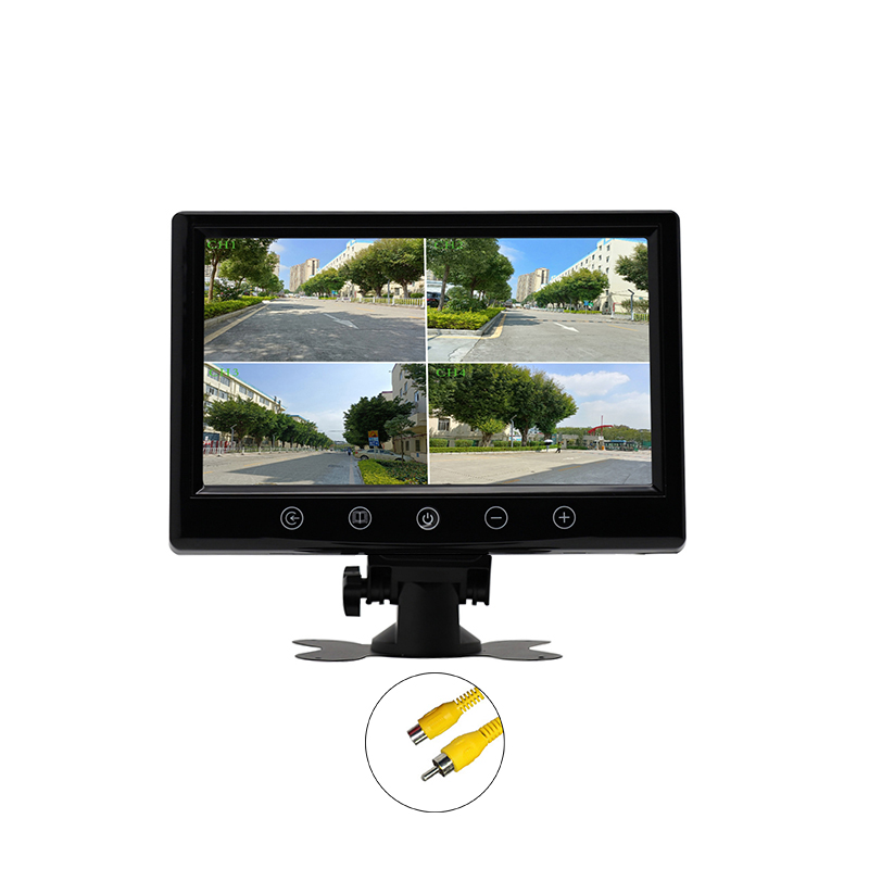
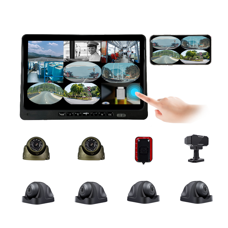
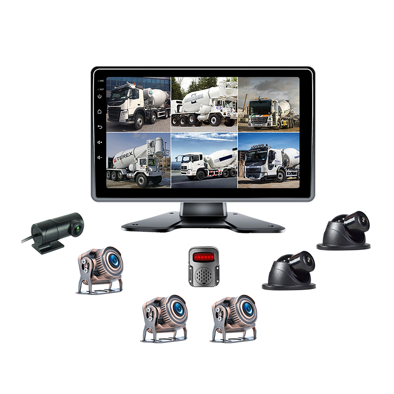
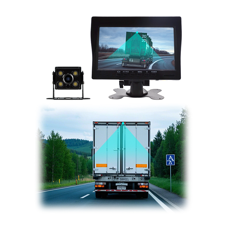
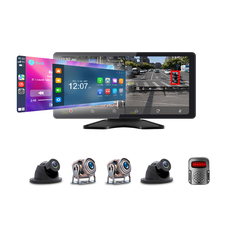
The screen commonly splits between the composite and a single native camera, side by side. The composite gives position, the full ring around the body at a glance. The native feed gives detail along the direction of travel, undistorted and conventional in shape, with guide lines overlaid. Drivers work the pair together: the ring for clearance all round, the single view for the dock edge or the trailer mouth ahead of the bumper.
The commercial duties lean on the view harder than the saloon car that introduced it. A bus pulling into a kerbside stop reads the gap to the kerb along its whole flank in one glance. A tipper reversing to a hopper reads the tail swing against the structure. A tractor unit backing under a trailer reads the kingpin line. A van in a courtyard reads the children’s bicycles below its window line. Each is a task mirrors serve badly and the ring serves directly, the duty list that put the system on commercial bodies.
Overlays ride on top of the composite where fitted. Steering-linked path curves, distance bands and the warning markers of the driver-assistance systems all draw in the same top-down coordinates, the fused display the twelfth sibling page treats. The composite is the canvas those systems share, one more reason its geometric honesty under the assumption above is the property everything else leans on.
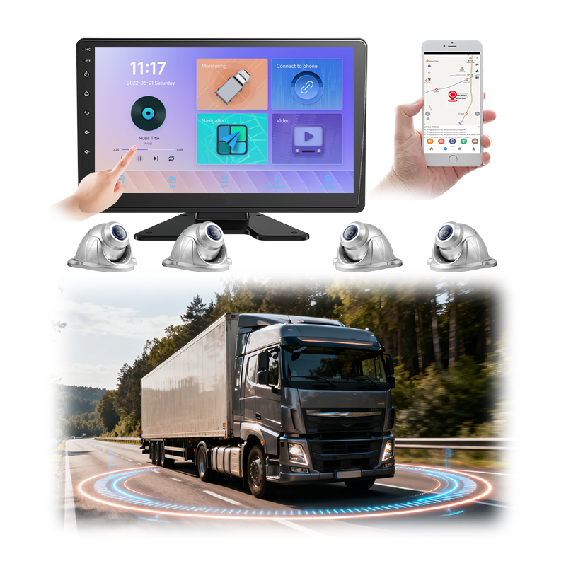
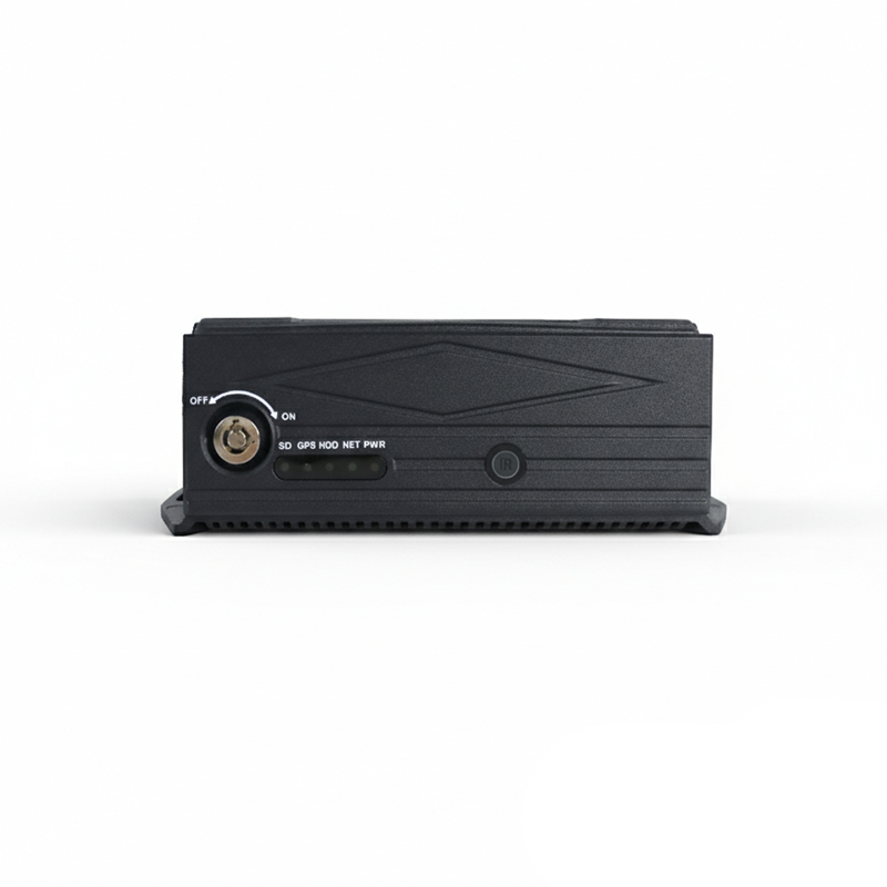
The pipeline runs entirely on the vehicle’s own processor, camera to screen, with no network step anywhere in it. The series’ recording pages established that rule for evidence. The same rule holds here for a harder reason: the view serves live steering. Steering tolerates none of the delays a link can add. The frames move over internal wiring, the composite renders locally, the screen sits centimetres from the processor that drew it.
The processing load sits comfortably inside the SoC class the terminal market builds on. Four streams of undistortion, transform and blending run as fixed per-pixel mappings once calibration sets them, the kind of work the same chips’ video engines and graphics blocks do at line speed beside the encoders the codec pages describe. The pipeline costs a known slice of a known chip, sized at design, with no growth in service: the same frames, the same mappings, every cycle.
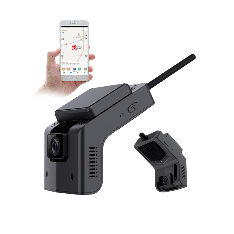
The network meets the bird eye view only as a consumer, on the series’ standing classes. The four raw camera feeds can record to the card like any other channels, on the storage arithmetic the recording pages price per channel and per day. The composite can stream to a platform as a live view at a configured tier, ride an alarm parcel as evidence stills of the moment around the vehicle, or stay entirely local, each one a configuration line in the classes the trade-off page sorts by reader and by size. Nothing about remote viewing touches the on-vehicle loop that steers.
The first look is a walk around the parked vehicle with the view up. One person circles the parked body carrying any tall object, a cone, a broom, themselves, while a second person watches the screen. The walker should remain continuously visible through the whole circle, smearing as the geometry says, doubling briefly at the corner seams at worst, vanishing nowhere. A disappearance anywhere on the circle names a coverage gap or a dead feed before any measurement starts.
The ground tells the alignment story with paint and a tape. Park across a straight painted line and read it on the composite: one continuous line through all four camera zones, no step and no kink at any seam. Lay a tape outward from the body side and check the screen’s distance bands against the real metres on the ground. Stand the cone at a marked spot inside each corner overlap and confirm its root sits on screen where the mark sits in the yard. Steps, breaks and offsets name calibration work, the regimes the calibration sibling pages own.
The walk has a repeat list, written next to its photographs. Any camera removed, refitted or knocked re-runs the walk before the vehicle works, because the registration stage trusts positions that may have moved. Body repairs near a mount re-run it. A screen complaint from a driver re-runs it ahead of any deeper diagnosis, fifteen minutes against the same filed photographs separating a moved camera from a complaint with another cause. The triggers mirror every revisit list this series keeps beside its numbers.
The sprite check ends the walk. Measure the body’s real width and length against the drawn outline’s claimed footprint, bumper to drawn bumper, mirror to drawn mirror. Open each door and confirm what the outline hides matches what it claims to hide. The whole walk runs in fifteen minutes with a cone, a tape and the yard’s existing paint. It files as photographs of the screen beside photographs of the ground, then repeats after any camera is disturbed, the acceptance habit every mechanism page of this series ends on.
The camera line names the count of four, the fields of view past one hundred ninety degrees, the mounting points marked on the body drawing and the synchronised capture requirement across all of them. The pipeline line names the stages as delivered functions: undistortion against a measured lens profile, ground-plane transform, registration from recorded calibration, seam blending in the overlaps, composite output with a body-matched sprite. The duty line names the boundary: near-field low-speed views, with triggers stated, with the above-ground artifact behaviour described in the operator documentation ahead of service.
The acceptance line names the walk: continuous visibility around the ring, painted-line continuity across seams, distance bands against tape, sprite footprint against the body, filed with photographs. The deeper numbers stay with their owners, latency and frame rate with the optimisation page, seam grading with the seam page, calibration tolerances with the calibration pages, the division this overview exists to map.
Specify four synchronised fisheye cameras past one hundred ninety degrees at the four faces, with corner overlap stated. Require the six pipeline stages as named functions with a measured lens profile and recorded calibration behind them. Require a body-matched sprite with its footprint dimensions written in the commissioning record. Write the above-ground artifact paragraph into driver induction. Run the fifteen-minute walk at acceptance and file the photographs. The screen then shows what the geometry can honestly show. The fleet knows exactly where honesty ends. Every deeper question already has its page.
Four fisheye cameras on the body, front, rear and both sides, each see more than one hundred ninety degrees of the near field. The system straightens each frame against the lens’s measured curvature, re-projects it onto the ground plane as seen from above, aligns the four patches on one grid using recorded calibration, blends the corner overlaps where two cameras see the same ground, then renders the result around a stored top-view graphic of the vehicle. The overhead viewpoint is computed, frame by frame, on the vehicle’s own processor, with the sequence repeating for every displayed frame.
The projection assumes everything lies flat on the road. Ground features obey the assumption and land exactly. Anything above the ground gets cast outward along the line away from the camera, feet placed correctly, the body smeared radially, the taller the object the longer the smear. The trust gradient follows height: centimetres honest, knee height leaning, head height smeared. At corner seams two cameras smear the same object in two directions, which can briefly double it as the seam logic picks or blends. The behaviour is the geometry working. The root of the object on the ground stays trustworthy, the one paragraph of driver training the system asks for.
No. No camera sees the vehicle’s own roof, so the centre is a stored top-view graphic scaled to the body’s footprint at commissioning. The drawn outline is what the driver steers by, so its dimensions are checked against the real body at acceptance with a tape. Overhanging loads, open tail lifts and anything outside the stored outline sit in the cameras’ blind hole and never appear on the screen. Bodies that change shape in service belong to the articulation and trailer pages of this series.
Near-field, low-speed work: parking, dock approaches, tight-yard manoeuvring, pull-away checks around the wheels and bumpers. The view triggers on reverse gear, low speed thresholds or turn indicators and retires above walking-pace bands. The crisp zone covers the metres beside the body where mirrors cannot reach, softening outward as each camera’s edge pixels thin. Kerbside stops, dock approaches and kingpin lines are the commercial duties the ring serves directly. Highway-speed perception belongs to other sensors and other pages of this series.
No. The whole pipeline, capture to screen, runs on the vehicle’s own processor over internal wiring, because live steering tolerates no link delays. The network only consumes the result where configured: the raw channels can record to the card, the composite can stream as a live view at a configured tier or ride alarm parcels as evidence stills, on the same traffic classes the rest of this series prices page by page. The steering loop never touches the radio, and the pipeline’s load sits as a fixed slice of the terminal’s own chip.
A fifteen-minute walk with a cone and a tape. One person circles the parked vehicle and must stay continuously visible on screen through every seam. A painted line read across all four camera zones must run unbroken, with no step at any join. Distance bands check against real tape metres, a cone’s root against marked spots in each corner, the sprite’s footprint against the measured body. Photographs of screen and ground file together. The walk repeats whenever a camera is disturbed, after body repairs near a mount and ahead of any deeper diagnosis of a driver’s screen complaint.