

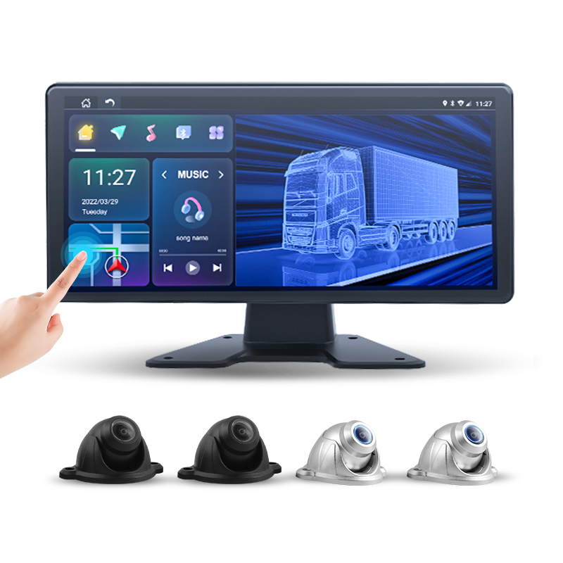
The bird eye view on a fleet vehicle’s screen is assembled from four overlapping pictures. The assembly can betray itself in two distinct ways: lines that break where the pictures meet, color that changes from one region of the composite to the next. The line breaks are a geometry fault. The color changes come from camera settings. Both show at the same place: the seams.
Each of the four cameras delivers its patch of ground to a shared grid. At the four corners of the vehicle, the patches overlap: the front camera and the right camera both photograph the wedge of ground off the front-right corner, at full resolution, from different positions. Every ground point in that wedge arrives twice. The composite has one screen pixel to spend on it.
The overview page of this series walked the whole pipeline in six stages and spent one sentence on this one. The calibration page measured each lens’s bend and each camera’s position, the inputs the seams consume. What remains is the narrow strip where two corrected, projected, registered pictures finally touch. Two jobs are done there: choosing where one picture hands over to the other and making the two halves agree about brightness and color.
Two cameras see the same strip of ground. The screen shows it once.
The overlap regions are set by the camera geometry the calibration page measured. Four lenses with fields of view past 180 degrees, mounted at the front, the rear and the two mirror arms, leave a wedge of double coverage at each corner of the body. The size of each wedge follows from mounting height and angle: higher cameras and wider lenses produce deeper overlaps. On a long rigid body the corner wedges are broad at the corners and the side cameras carry long single-coverage strips between them.
The composite consumes the overlap in a fixed pattern. In production implementations, every output pixel of the bird eye view is generated by fetching source pixels through a geometric lookup table: one source pixel where a single camera covers the spot, two source pixels where the spot sits in an overlap. The fetched values pass through photometric correction and a weighted blend before landing on the screen. The table is built at calibration time. At runtime the pattern of single and double fetches never changes.
The two fetched values describe the same square of ground. A perfect system would fetch two identical values. Real ones disagree in two separate ways. They can disagree about position: the same painted line lands at slightly different grid coordinates through the two cameras. They can drift apart in appearance: the same gray asphalt arrives brighter through one camera and bluer through the other. The two disagreements have different causes, different cures and different fault signatures.
The first source is calibration residual. The measurement session that produced each camera’s lens profile and position reported its quality as a reprojection error, healthy at a small fraction of a pixel. Small is not zero. Each camera’s projection carries its own residual into the overlap. The two residuals point in unrelated directions. A line that projects a few millimeters north through the front camera and a few millimeters east through the side camera shows a small step exactly at the handover.
The second source is the ground assumption. The projection maps every pixel onto the ground plane, the working assumption the overview page explained. Anything above the ground breaks it: a bollard standing in the overlap projects to one ground position through the front camera and a different ground position through the side camera, because the two cameras view it from different places. The overlap shows the bollard twice. The doubling is not a calibration fault. It is the geometry of viewing one raised object from two positions, present in every healthy system.
The third source is mechanical drift. A bracket nudged in a depot wash, a mirror arm loosened by vibration, a body repair near a mount: each moves a camera from its recorded position. The recorded projection no longer matches the physical one. The seams report it first. A step that appears on a previously clean seam and stays there through all light conditions is a moved camera until proven otherwise, the revisit trigger the calibration page’s record delta exists to confirm.
The three sources separate by behavior. Residual misalignment is small, constant and present from commissioning day. Parallax doubling appears only on raised objects, grows with their height and is absent on flat paint. Drift appears suddenly, persists and grows with further mechanical insult. Painted ground markings are the cleanest probe: flat by definition, they should cross a healthy seam without a step, the reason the acceptance section below stands the vehicle on parking-bay lines.
Each camera runs its own exposure, its own white balance and its own tone mapping. The published harmonization work states the root cause plainly: image color and tone differ between cameras because each applies auto white balance and global tone mapping individually. Nothing synchronizes the four decisions by default. Four small computers each pick the rendering they judge correct for their own view.
Because the four views differ, the four decisions diverge. The front camera faces a sunlit yard. The rear faces a shaded wall. The left side sits in the body’s own shadow band. Under depot lighting, the lamp reflections on wet asphalt fill one camera’s view. Each auto exposure converges on its own gain, each white balance on its own color temperature. The same concrete reads pale gray through one lens and blue gray through its neighbor.
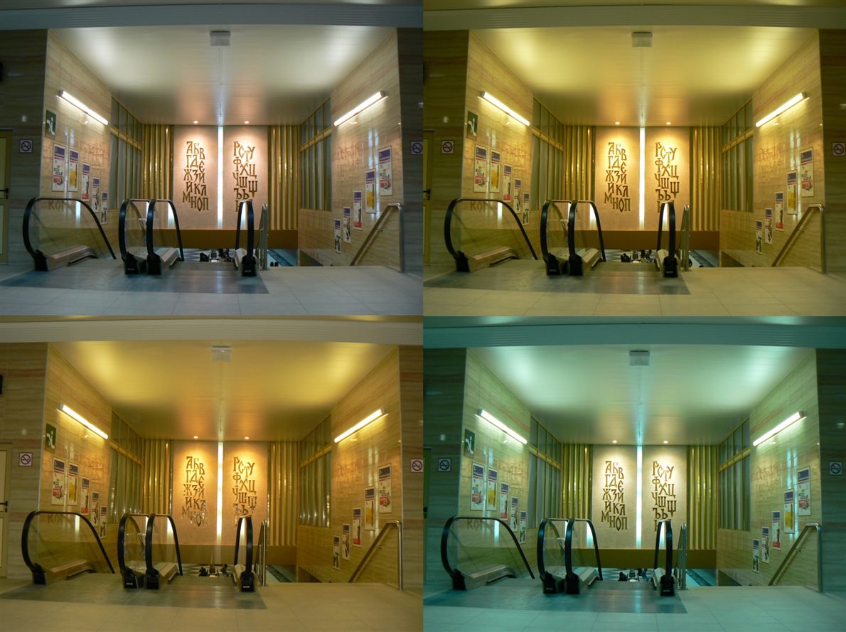
The collage alongside shows the size of the effect with a single camera: one stairwell, four white balance settings, four unmistakably different pictures. A surround system reproduces that collage across one image, with the boundaries running down the middle of the screen. The composite’s overlap regions inherit the mismatch directly: the two fetched values for one ground point arrive in two different renderings.
Color mismatch leaves geometry intact: the lines stay continuous, the distances true, the legal content of the view whole. What it breaks is the reading. A brightness step along a seam reads as a change in the pavement. A color cast on one quadrant reads as a wet patch or an oil stain. The driver’s eye spends attention separating rendering artifacts from road facts, attention the view exists to save.
Inside each overlap, one line decides the handover: ground on one side of it renders from the first camera, ground on the other side from the second, with a blend band straddling the line. The seam line’s placement is a design decision recorded in the lookup table. Two policies exist.
The fixed policy draws the line once, at integration. The common choice runs it diagonally through the overlap, roughly bisecting the wedge, kept clear of the vehicle sprite’s edges where projected resolution is at its thinnest. A fixed line keeps the lookup table static and the per-frame cost flat, the same compute-budget discipline the overview attached to the whole pipeline. Where the line sits becomes a known property of the product: the same corner of the screen, every trip, every frame.
The dynamic policy moves the line each frame. A published method computes a cost map over the overlap, finds the minimum-cost path through it and places the seam along that path, with blend weights computed from each pixel’s distance to the found seam. The cost is built to be low where the two views agree and high where they differ. The found seam threads around raised objects and zones of disagreement, the regions the map marks costly. A pedestrian standing in the corner wedge gets a seam that bends around the body. A fixed line in the same scene cuts straight through it.
The dynamic seam avoids the artifact and spends computation every frame to do it. Its seam position stops being predictable: a review of recorded clips sees the join wander from frame to frame. Commercial vehicle systems built to a fixed compute budget commonly ship the fixed line, with the dynamic option living in implementations with headroom. The specification line at the end of this page asks which policy a quoted system runs, in writing.
The crudest handover is a hard cut: pixels left of the line from one camera, pixels right of it from the other. Every residual difference between the two renderings then lands on one pixel-wide boundary. A brightness mismatch of a few percent, invisible spread over a band, prints as a visible line down the composite. Hard cuts survive only in systems whose color loop holds the two sides matched at all times.
The standard handover is a linear blend. A band straddles the seam line. Across it the output mixes both sources: weight for one camera fades from one to zero as distance from the line grows on the other camera’s side. The published embedded implementation stores the mixing weight for every pixel pair in a blending lookup table beside the geometric one. The runtime cost is a multiply-accumulate per pixel, on budget for the same imaging hardware the correction stage uses.
Band width is a real tuning decision. A wide band spreads any remaining brightness mismatch across many pixels, below the eye’s step-detection threshold. The same wide band doubles raised objects more gently and more broadly: the bollard that appears twice in the overlap renders as two soft half-transparent copies across the whole band. A narrow band sharpens the doubling into nearly one object and concentrates any color mismatch back toward a visible line. No single width fixes both. Implementations pick by what their color loop leaves behind.
Ground markings sample the trade on every trip. A painted line crossing the band renders as a mix of its two projections. With healthy geometry the two projections agree and the line passes clean. With a small residual step, a wide band renders the line slightly soft at the seam, the gentle version of the fault. A narrow band renders it doubled, the honest version.
A multi-band blend exists above the linear one: the overlap is split by spatial frequency, coarse content blended across a wide band and fine detail across a narrow one, taking the gentle treatment for color and the sharp treatment for edges at once. The published solution lists it as the costlier option in memory traffic. Fleet-grade systems mostly settle for linear blending plus a working color loop. The next section explains the loop.
The color cure is a feedback loop that levels the four renderings before the blend ever sees them. Every stage of the published mechanism exists for a stated reason. The loop begins with samples: in each of the four overlap regions, the system collects pairs of values, one from each of the two cameras viewing the region, taken from corresponding patches of ground. Production methods average a block of pixels on each side before comparing, because a few millimeters of geometric residual would otherwise pair a white line’s pixel in one view against asphalt beside it in the other and feed the loop nonsense. Block averages wash the misalignment out and leave the photometric difference, the quantity at issue. From the sample pairs the system estimates one multiplicative gain per camera per color channel, red, green and blue solved independently, because a white balance disagreement is a disagreement between channel ratios: matching the red channels and the blue channels separately is what aligns color temperature, the way matching all three together aligns plain brightness. The estimation is a joint optimization across all four cameras at once. The four overlaps chain the cameras into a ring, front to right, right to rear, rear to left, left back to front. The cost function minimizes the residual difference over every pair in the ring simultaneously. The ring structure is the reason there is no reference camera: a naive scheme that picks one camera as the standard and aligns neighbors to it in sequence accumulates error along the chain and dumps the total on the last seam, where the loop closes. Joint estimation spreads the closure error evenly around the ring, every seam carrying an equal, minimal share. The published method constrains every gain to one or above to keep corrections clear of clipping and solves the constrained problem iteratively, each camera’s gain refined while the others hold. Gains correct proportional differences only. A second stage follows for the rest: a piecewise linear tone curve per camera, anchor points spread evenly over the sample range, fitted to the residual the gains left behind, with a regularization term that keeps the curve from wandering far from the gain-corrected baseline. The gains repair the channel ratios. The curve repairs the remaining shape. The loop runs on in service. Statistics refresh as the light changes, corrections updating gradually enough that the screen never visibly pumps. Four pictures enter the blend already agreeing. The band has only geometry left to smooth.
A second route attacks the cause itself. The mismatch is born inside the cameras, in each one’s own white balance and tone mapping decisions. Recent published work harmonizes those decisions directly: for each adjacent pair, the white balance gains of both cameras are steered toward the pair’s average. The global tone mapping curve, held as a 256-point table, is interpolated toward the average table the same way.
The steering varies across the image. Each camera keeps its own rendering at the center of its view, where it is the sole source. Toward the boundaries it shares with neighbors, it approaches the harmonized rendering. The published method shapes the transition with a logistic curve running from one at the image center to the blended value at the edge. A camera facing genuinely different light keeps a correct exposure at its own center and agrees with its neighbors in the strip where agreement shows.
The measured appeal is cost. Steering parameters skips the overlap statistics, the patch analysis and the reference-camera sensitivity of the pixel route. The published implementation reports the harmonization step at 0.26 milliseconds on an automotive processor against 0.52 for the patch-comparison alternative it replaced. The two routes stack in practice: parameters narrow the disagreement at the source, the pixel loop of the previous section levels what remains.
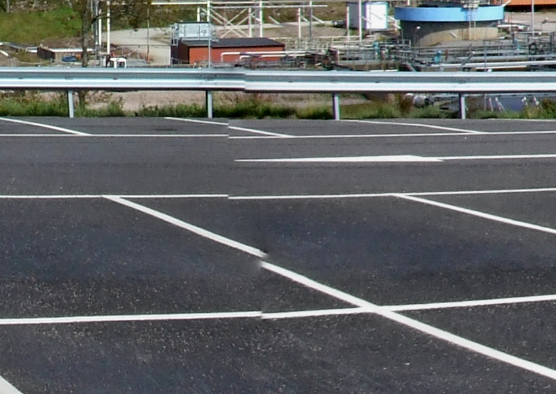
Seam faults sort into three families by sight. Each family names its own repair. The panorama alongside shows the first: lines that break sideways at the join. On the vehicle screen the same fault is a parking-bay line stepping where two cameras hand over, or a curb arriving twice as soft twins inside the blend band on flat ground where no raised object explains it. Broken and doubled geometry is the position family. Its home is the calibration page: a residual grown past its recorded value, or a camera moved off its recorded pose.
The second family is the brightness step. Lines cross the seam unbroken, the ground turns lighter on one side, as if the pavement changed batch along a ruler-straight edge. A straight tonal edge that tracks the seam position is the gain side of the color loop lagging or failing. The third family is the color cast: one quadrant of the composite renders cooler or warmer than its neighbors, the white balance side of the loop, the collage fault from the earlier section playing out live.
Time behavior separates the families further. Position faults arrive with mechanical events and persist through every light condition until someone re-measures. Brightness and cast faults drift with the light and heal when the loop catches up: a step that appears as the vehicle turns out of a floodlit gate and fades within moments is the loop doing its job at its own pace. A cast that sits on one camera all shift, in all light, is that camera’s white balance pinned or its statistics starved, a job for a settings bay.
The sorting belongs in the workshop manual because the repairs do not overlap. A color fault never needs the calibration cloth: the measuring session the calibration page describes fixes geometry and writes poses. Re-measuring repairs nothing in a white balance decision. A settings reset moves no camera. One look at the seam, sorted into the right family, routes the vehicle to the right bay on the first booking.
Night work stresses the color loop hardest. Gains ride high, the four cameras’ noise floors rise unevenly. Inside the blend band two noise textures mix into a faint shimmer that clean daylight never shows. Headlight beams and sodium lamps hand the white balance decisions extreme inputs. The low-light page of this series owns the full treatment, sensor choices included.
Weather attacks the inputs. A droplet or a mud film on one lens feeds the statistics a smeared sample. The loop drags a healthy camera toward a dirty one’s rendering. Lens contamination and image degradation in rain and snow belong to the weather page. The seam behavior of an articulated joint belongs whole to the articulation page.
The seam checks slot into the same fifteen-minute acceptance walk the overview specified, with three items aimed squarely at this page. The first is the walking figure: one person walks a slow lap of the vehicle while a second reads the screen. The figure must stay single and continuous through all four corner handovers, allowing the soft doubling the geometry produces for a raised body inside the band, with no vanishing, no teleporting and no second copy on the ground plane.
The second item is painted geometry. The vehicle stands on bay markings. Every line crossing every seam is read for steps, kinks and width changes. The third is tone: the four quadrants of the composite should read as one continuous surface, no straight tonal edges tracking the seam positions and no quadrant with its own color temperature. Both items take seconds on the screen the figure check already uses.
The walk repeats on the calibration page’s triggers, after camera work, body repairs or a failed daily glance. Between formal walks, the driver’s daily version is one look: does the picture still read as one image. The fault families from the previous section turn anything the look catches into the correct booking, color faults to a settings bay, position faults to the cloth.
Four lines carry this page into a purchase document. The seam line states the seam policy, fixed or dynamic, the blend approach, hard, linear or multi-band, the chosen band width beside them. The color line states the harmonization mechanism, overlap-statistics loop, parameter steering or both, with the update cadence beside it. The acceptance line adds the three seam checks, walking figure, painted lines and tone uniformity, to the commissioning walk and to every post-repair revisit. The fault line puts the three-family sorting table in the workshop manual, where the first person to see a bad seam finds the right booking.
Each line costs a paragraph to write. Skipping one surfaces months later as a recalibration van sent to fix a white balance, or a settings reset applied to a bent bracket. Geometry joins the four pictures. Color makes them one image.
Each of the four cameras runs its own exposure, white balance and tone mapping. Each faces different light: one into sun, one into the body’s shadow, one into lamp glare. The four decisions diverge. The composite inherits the disagreement as visible regions, brightest along the seams where two renderings meet. The cure is a harmonization loop that levels gains and color channel by channel across the four-camera ring, with parameter steering inside the cameras as the complementary route. A persistent single-quadrant cast points at one camera’s own settings, with the shared loop healthy.
At each corner of the vehicle, two cameras photograph the same wedge of ground. The seam is the line inside that overlap where the composite hands over from one camera to the other, with a blend band straddling it in which both sources mix at weights that fade with distance from the line. The line’s placement is fixed at integration in typical fleet systems, or computed per frame along a minimum-difference path in dynamic implementations. The band’s width trades softer color steps against broader doubling of raised objects.
The projection maps every pixel to the ground plane. A raised object in an overlap is seen from two different camera positions. Each camera’s ground projection drops it in a different place. The blend renders two soft copies. The doubling is the geometry of two viewpoints, present in a perfectly calibrated system, strongest for tall objects close to a seam. Flat markings show no such doubling. Painted lines that break or double at a seam indicate a real fault, in residuals or a moved camera. Parallax cannot produce them on flat paint.
The published mechanism samples corresponding ground patches in each overlap by block average, estimates one multiplicative gain per camera per color channel under a joint optimization over the full four-camera ring, applies a constraint against clipping and follows with a piecewise linear tone curve per camera for the residual the gains leave. Ring-wide joint estimation avoids a reference camera and spreads closure error evenly across all four seams. A parameter route steers each camera’s white balance and tone mapping toward its neighbors near shared boundaries. Production systems can run both.
No. The band mixes two projections across its width. A geometric step renders inside it as a soft double image. The softness is cosmetic: distances read off a misaligned composite stay misaligned at any band width. The band’s legitimate job is smoothing the small residual differences a healthy system leaves behind. Lines that double or step at a seam are a measurement fault. The repair is the calibration session.
Three items, on top of the standard walk. A walker laps the vehicle and must stay single and continuous through all four handovers. The vehicle stands on painted bay lines and every line must cross every seam without steps, kinks or width changes. The four quadrants must read as one surface, with no straight tonal edge tracking a seam and no quadrant holding a color cast of its own. The checks repeat after camera work or body repairs. The daily driver version is one look for one image.