

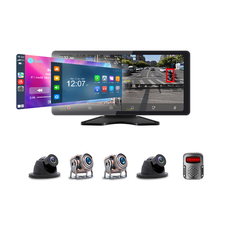
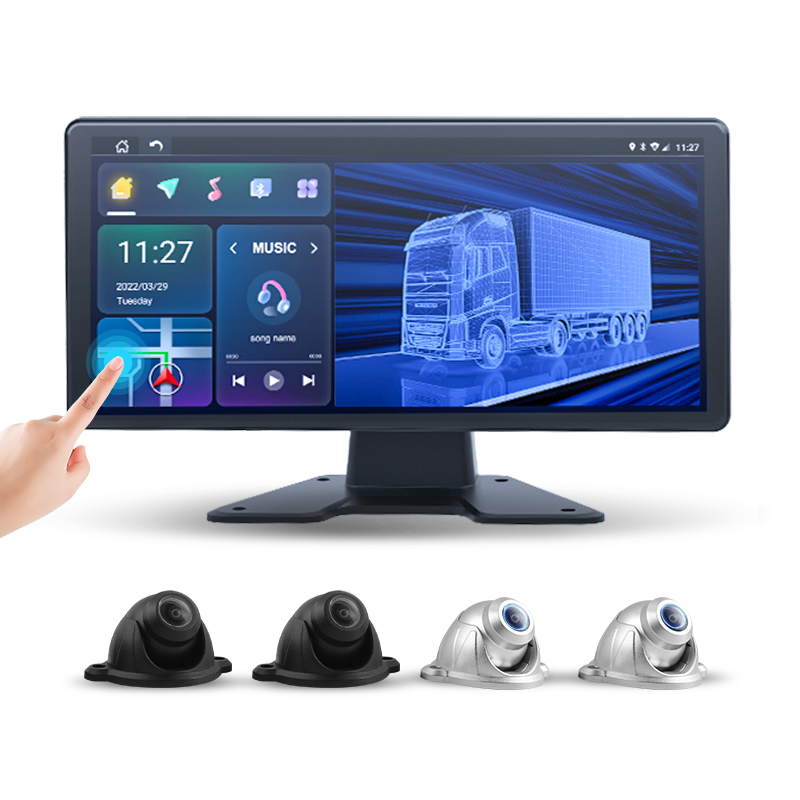
A fisheye camera bends the world by a fixed rule, the same bend in every frame for the life of the lens. Correction is the application of that rule backwards, per pixel, in real time. The rule itself has to be measured before it can be reversed. The measuring instrument is a printed sheet of known geometry laid on the ground: the calibration cloth. The pipeline page of this series named this stage in one paragraph. This is the page that unfolds the cloth, runs the session and reads the numbers it produces.
The two halves of the title are one process. Distortion correction is the runtime half: a remapping table the processor applies to every frame, moving each pixel from where the lens put it to where a straight-lined world would have put it. The cloth is the measurement half: the known pattern that lets the system work out, once, what that remapping table has to be for each individual lens on each individual vehicle.
The split matters to a fleet because the two halves fail differently. The runtime half is fixed silicon arithmetic that does not drift: once the table is right, it stays right. The measurement half is a physical procedure with cloths, distances, floors and people in it. Every wrong number it produces gets faithfully applied to every frame afterwards. The session is where accuracy is won. The runtime only preserves whatever the session achieved.
The boundaries follow the sibling map the pipeline overview drew. The mathematics of projecting corrected frames onto the ground plane belongs to the transform page. The question of whether calibration happens once at fitting or refreshes itself in service belongs to the regimes page. What belongs here is the lens’s own profile, the cloth that measures it and the session that turns one into the other.
The lens bends by rule. The cloth measures the rule.
A fisheye lens maps a near half-sphere of world onto a flat sensor. The mapping is a smooth, fixed function of angle. Light arriving close to the lens axis lands near the frame centre with little displacement. Light arriving from far off-axis lands compressed toward the rim. The published lens families differ in the exact curve they follow. Manufacturing tolerances move each individual lens a little away from its family’s nominal curve. The curve that matters is the one this lens has.
The profile is described by a short list of numbers. Where the optical centre lands on the sensor, never exactly the geometric middle. How strongly the bend grows with angle, captured in a handful of coefficients that bend a nominal model to fit this lens. The numbers are few enough to print on a label and precise enough to place corrected pixels within fractions of their width, the resolution the seam and transform stages downstream depend on.
The profile holds still over the lens’s life. Because of that stillness, one session’s measurement can stand for the part’s whole service. Glass and moulded optics keep their curve through the temperatures and vibrations of vehicle duty, with the coefficients drifting only when something physical changes: an impact, a remount stress, a replacement part. The profile is a property of the part, the reason the failure triggers in this series are all mechanical events and none of them are dates.
Per lens means per camera, four times per vehicle. Two cameras of the same part number differ enough that sharing one profile between them visibly misplaces the ground near the frame edges, exactly where the composite stitches. Production systems store four profiles for that reason, keyed to camera positions, written during the session below and carried in the configuration records the series’ parameter pages manage.
Correction at runtime is a lookup, deliberately dumb. From the measured profile the system computes, once, a remapping table: for every pixel of the corrected output frame, the table names the spot on the raw fisheye frame the value comes from. Producing a corrected frame is a sweep through the table, the per-pixel fetch-and-place work the pipeline page located in the SoC’s imaging blocks at line speed.
The dumbness is the design’s reliability. No detection, no estimation, no scene understanding happens at runtime: the same table runs on a sunny yard and a black night, on an empty road and a crowded dock. The corrected frame’s quality cannot decay in service, because nothing in the correction depends on service conditions. The only way correction goes wrong is the table being wrong. A wrong table is the session’s responsibility, the division the opening laid out.
The table regenerates only when its inputs change. A new lens profile after a camera swap, a new pose after a recalibration, a resolution change in the pipeline configuration: each rebuilds the table once, at configuration time, on the vehicle. Nothing rebuilds in traffic. The rebuild takes the processor moments and the record notes it, the same configuration-event logging every parameter page of this series expects.
The table holds the resolution trade the overview admitted. Because the fisheye’s rim pixels cover more world per pixel than its centre pixels, the corrected frame’s outer regions are interpolated from thinner data. The remap cannot create detail the sensor did not record. Correction straightens geometry and preserves the unevenness, the honest order of operations the composite’s softer outer ring displays.
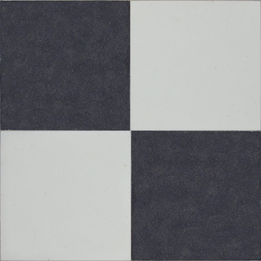
Measuring a lens means showing it something whose true geometry is known and reading where the pixels land. The surround-view literature settles on ground patterns of corners, circles or lines: high-contrast features a detector finds reliably, spaced at distances the pattern’s manufacture guarantees. A chequer of black and white squares is the common choice, because every interior corner is a sharply defined point and one laid grid supplies hundreds of such points in positions the print guarantees.
The cloth is the practical carrier of that pattern at vehicle scale. A printed mat rolls out flat, carries its dimensions with it wherever the vehicle is, then lays the known grid on any reasonable floor: the fitting bay today, a depot in another city next year. Painting the same pattern onto a workshop floor serves a fixed production line that calibrates vehicles daily, the factory case the literature notes in passing. A fleet that calibrates at fitting and after repairs wants the geometry portable. The cloth packs that geometry into a tube.
The cloth’s known geometry serves both halves of calibration at once. The same detected corners reveal the lens’s bend and where the camera stands in one capture: a camera mounted higher sees the grid smaller, one angled down sees it foreshortened, one rotated sees it turned. One layout, one capture, two families of numbers solved together, the intrinsic profile this page owns and the extrinsic seed the registration stage spends. The economy is the reason the session solves everything in one pass.
The pattern carries its own orientation marks. Plain chequers look the same rotated or mirrored. Because of that symmetry, production patterns add asymmetric features, coloured dots in published designs, that tell the detector which way is forward and which corner is the origin. The marks let the system know which cloth it is seeing and which camera should be seeing it, the bookkeeping that makes a four-cloth layout solvable in one pass.
The kit is cloths, a dimension sheet and the small hardware that keeps the geometry honest on the day. Typical kits carry several mats: one per camera face, sized so each camera sees its pattern large in the frame at the stated distances, with kit variants per vehicle class, the van kit smaller than the coach kit, the sizing difference the heavy-vehicle page picks up in its own terms. The print is matt to refuse glare, high-contrast to feed the detector, dimension-stable so the squares stay the size the sheet claims.
The dimension sheet is the kit’s standing authority. It states the square size, the grid counts, the required distances from named body reference points to cloth edges and the required gaps between neighbouring cloths. The session’s solver assumes those numbers are true. A kit used with another kit’s sheet, or a sheet misread by a centimetre, produces a confident calibration of the wrong world, the distance family of failures the list below prices.
The keeping-honest hardware is mundane on purpose: a tape measure for the stated distances, weights or pins against wind and curl, chalk for marking wheel and cloth positions so a later session can repeat the same geometry on the same floor. Some kits add a straight edge for checking floor flatness along the cloth lines where doubt exists. Nothing in the kit is electronic. The electronics stay on the vehicle, the kit carries only print, weights and tape.
The layout puts known geometry in front of every camera at once. The common arrangement lays a cloth ahead of the front camera, one behind the rear, one along each flank under the mirror cameras, each at the sheet’s stated distances from the body reference points, square to the vehicle’s axes. Corner-spanning arrangements place patterns in the overlap zones instead or as well, feeding two cameras one shared truth, the strongest input alignment can get.
The corner-spanning variant carries extra mats for bodies where seams matter. A pattern placed diagonally in each overlap zone is seen by two cameras at once. The solver receives the same physical corners through two lenses, the direct constraint that pins neighbouring cameras to each other on top of pinning each one to the ground. Kits for long bodies ship the extra mats for this reason, with the dimension sheet stating both layouts.
Square and flat are the two words the whole layout serves. Square, because the solver reads the cloth edges as reference directions: a cloth laid at a small angle reports a camera at a small angle. The composite inherits the twist. Flat, because the pattern is trusted as a plane: a wrinkle is a false hill, a curled corner is a false slope. The solver will faithfully bend the world to match. The session checklist spends the bulk of its lines on these two words.
The vehicle’s own position closes the geometry. The body stands centred and straight on the layout, at marked wheel positions, with suspension settled and the body unloaded the way the dimension sheet specifies. The solved camera positions are positions relative to this body stance. A vehicle calibrated nose-high on a ramp carries that ramp in its view for the rest of its service, the slope case the failure list below prices in full.
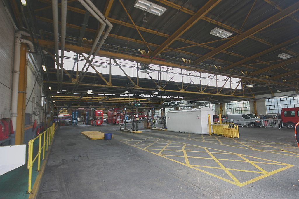
The session is six steps. A disciplined crew runs it in well under an hour. Step one prepares the venue: a flat stretch of floor large enough for the vehicle plus its cloth margins on all four sides, even light without hard sun stripes, the broom run over the whole layout area. The bus-garage class of floor is the natural venue, the reason calibration work lives at fitting bays and depot halls, the same venues every other measured procedure in this series uses. Step two lays the geometry: cloths at the sheet’s stated distances, taped and weighted, every distance measured twice; the vehicle driven to its chalk marks, straightened, settled. Step three is the capture: the system grabs synchronised frames from all four cameras with the patterns fully in view, the orientation marks identifying which cloth belongs to which camera in the layout. Step four is detection: the software finds the pattern’s corners in each frame to sub-pixel precision, building hundreds of point correspondences between image positions and the true grid the dimension sheet declares for each mat. Step five is the solve: from those correspondences the system fits each lens’s profile, the optical centre and the bend coefficients of the intrinsic half, then seeds each camera’s position and mounting angle on the body, the extrinsic half the registration stage spends downstream. Published methods do the fit by driving the reprojection error down: adjusting the candidate numbers until the pattern corners, projected through the candidate profile, land on top of where the camera saw them in the captured frames. Step six writes the record: four lens profiles, four camera poses, the per-camera residual numbers, the kit identity and the date, into the configuration store the parameter pages manage, with the old record kept beside it for comparison. The crew is two people in practice, one measuring and laying, one at the screen driving the capture, with the second pair of eyes doubling as the wrinkle check the failure list demands. The settle conditions get their named minute: doors shut, parked brake on, nobody aboard, the suspension given its moment after the drive onto the marks, because a body that settles two centimetres after capture has moved its cameras by the same amount relative to the cloths. The session ends with the verification the numbers section describes, on the same cloths before anything is rolled up, and with the record’s delta against the previous session read aloud before the crew signs. A failed verification reopens the layout, with the per-camera residuals naming which mat to re-lay first, the loop running until the laid cloths read straight on the screen.
The wrinkle family is first because it is the commonest. A fold, a curl, a bubble under the cloth turns flat truth into false terrain. The solver bends the lens profile to explain it. The composite then bows straight lines near that camera. The cure is the kit’s weights and the crew’s eyes at cloth level, a squat and a sight along each mat before capture.
The distance family is the quiet one. A cloth ten centimetres closer than the sheet states, a tape read from the wrong body reference, a sheet from a different kit: the solve converges, the residuals look fine, the scale is wrong. The composite’s distance bands then lie by the same ratio everywhere, the error the acceptance walk’s tape check exists to catch. The two-measure rule in the session procedure exists for this family.
The slope family comes from the venue. A crowned yard, a drainage fall, a ramp under one axle tilts the true ground away from the assumed plane. The solve charges the tilt to the cameras. The composite leans. Floors flat to the dimension sheet’s tolerance, checked along the cloth lines with the kit’s straight edge where doubt exists, are the only cure.
The light family is the day’s weather indoors. Hard sun stripes across a pattern blow out white squares and bury corners in shadow edges the detector mistakes for geometry. Deep shadow under a high body hides the near rows. Glare from a wet or glossy patch erases contrast. Even, dull light is the request, the reason sessions prefer the garage to the open yard at noon.
The wear family closes the list. A cloth faded by sun, stained by oil, frayed at the corner rows feeds the detector weak or missing corners. Solves drift as point counts fall. The care section’s inspection habit retires cloths before they reach that state, on the same replace-by-condition logic the storage pages apply to cards.
The session’s first product is the reprojection residual, the average distance between where the solved model says pattern corners should land and where the cameras saw them. Implementations report it in pixels, with healthy sessions sitting at small fractions of a pixel and anything approaching whole pixels flagging a layout problem before any visual check begins. The residual is the session’s own confession, read before the cloths move.
The second product is the visual check on the still-laid cloths. The corrected, composed view should show the chequers as squares, the cloth edges as straight lines running unbroken through the seams, the four mats sitting square to the drawn vehicle. Bowed edges name a bad profile, stepped edges at seams name bad poses, trapezoid squares name slope or twist, each symptom pointing back at one failure family on the list above.
The residual reads per camera on top of the average. That split turns it into a pointer. Four healthy residuals with one outlier name the outlier’s camera: its cloth, its light, its mount. A crew that reads the four numbers separately walks straight to the one mat that needs re-laying, with three cameras’ work kept. The per-camera read is the difference between repeating a step and repeating the afternoon.
The third product is the record’s delta against the previous session. Camera poses that moved more than mounting tolerance since last time name a knocked bracket or a body repair, the same events the overview listed as revisit triggers. Profiles that moved name a lens change or damage. A clean delta is the usual outcome and the point of the read: the system measured today and found yesterday still true.
The cloth is a measuring instrument and lives like one. It travels rolled in its tube, stores dry and out of sun, with folding kept off the handling list. Cleaning is a wipe, with solvents kept away from the print. The kit list is checked complete after each session, because a missing flank mat next time becomes an improvised layout. Improvisation is how the distance family of failures gets in.
The kit has an owner, named in the procedure file. One workshop role holds the tube, the sheet and the replacement ordering, the same single-owner pattern the series gives SIM ledgers and key registries. A kit that lives in a named cupboard under a named role survives staff changes. A kit that floats between vans loses a flank mat by spring.
Inspection is one minute per session. Unrolled for use, each cloth gets a glance along its surface for fading, oil stains across corner rows, fraying edges and print cracking at the roll’s habitual stress lines from storage. The dimension sheet travels with the kit and gets the same glance, because a sheet swapped between kits is the quiet scale error waiting to happen. Condition findings retire the cloth and order its replacement, with the kit identity in every session record keeping the instrument history straight across the years.
The profile line requires per-camera intrinsic profiles measured on the assembled vehicle at fitting, stored keyed to camera position, with the measured residuals recorded beside them. The kit line names the kit: pattern type, mat count and sizes for the vehicle class, the dimension sheet’s identity, the venue’s flatness requirement. The session line requires the six steps as a written, signed procedure with the two-measure rule, the settle conditions and the verification on laid cloths before anything is packed up. The record line requires profiles, poses, per-camera residuals, kit identity and date in the configuration store, with prior records retained so every later session reads its delta against this one.
The lines land where this series always lands them. The profile and record lines sit in the commissioning documentation beside the camera positions and sprite dimensions the overview’s specification named. The kit and session lines sit in the workshop’s procedure file, the same shelf as the acceptance walk. The regimes page adds its own lines for what refreshes between sessions. Together they make the cloth session a documented measurement, repeatable by a different crew in a different city to the same numbers.
Specify per-lens profiles measured on the vehicle, with residuals stated and recorded. Buy the kit for the vehicle class, with the dimension sheet bound to it, an owner named for it and the flatness requirement written. Adopt the six-step session as a signed procedure, two measures on every stated distance, verification and the delta read on laid cloths before pack-up. File every session’s record beside the previous one and read the delta as part of the sign-off. The lens then bends by its rule. The table reverses it exactly. The composite downstream inherits geometry a tape measure can defend.
The lens maps a near half-sphere onto a flat sensor. That mapping bends: straight kerbs bow, poles lean, the world wraps toward the rim. The bend follows a fixed, smooth rule set by the lens design and the individual unit’s manufacture. Correction measures that rule once, builds a per-pixel remapping table from it, then applies the table to every frame in real time, handing the rest of the pipeline a straight-lined image to project and stitch. The table only changes when a camera or a calibration changes, with nothing scene-dependent in it.
A printed mat carrying a high-contrast pattern of known geometry, commonly black and white squares whose interior corners a detector can locate to sub-pixel accuracy, with asymmetric marks that declare which way is forward and which corner is the origin. Laid at stated distances around the vehicle, it shows every camera a truth whose dimensions are guaranteed by the print, the input the solver needs to recover each lens’s profile and each camera’s position in one session.
Two lenses of the same part number differ enough, through ordinary manufacturing tolerance, that one shared profile visibly misplaces ground near the frame edges, exactly where the composite stitches its seams. Production systems store four individual profiles keyed to camera position, written during the session and kept in the configuration record, with the optical centre and bend coefficients fitted per unit. Measuring on the assembled vehicle folds in whatever stresses the mounting placed on the part. The profile then holds for the part’s life, moving only on mechanical events.
Five families, each with its own cure. Wrinkles and curls turn the flat pattern into false terrain the solver trusts. Distance errors, a misplaced cloth or a misread sheet, scale the whole world wrong, with the numbers looking healthy throughout. Sloped venues charge the floor’s tilt to the cameras. Hard light stripes, deep shadow and glare starve the corner detector. Worn, faded or stained cloths feed it weak points. The session checklist exists to walk each family before capture, with the per-camera residuals naming the guilty mat after.
Three reads before the cloths roll up. The reprojection residual, the solver’s own error figure, sits at a small fraction of a pixel in a healthy session, read per camera to point at any guilty mat. The corrected composite shows the chequers square, the cloth edges straight through the seams, the mats sitting square to the drawn vehicle on the screen. The new record’s delta against the previous session shows poses and profiles unmoved beyond tolerance, with any larger move naming a knocked camera or a repair the workshop should already know about.
On triggers, with no calendar in it. Any camera removed, refitted or knocked. Body repairs near a mount. A failed acceptance walk, stepped lines at seams or distance bands off against the tape. A screen complaint that the fifteen-minute walk does not clear. Between triggers, the regimes page of this series weighs how much refreshing happens by itself without the cloth. The session record’s delta read keeps every return visit honest against the last one.